M202A Project
Useful Links
- Project Repo - follow the README for instructions on cloning and potentially building (although running will require the same hardware which I have)
- Project Presentation
Motivation
Motivated by work building racecars for the Formula SAE student competition, I want to develop a data logging system that can be used onboard a vehicle. The system will monitor the vehicle’s CANbus and log messages to non-volatile storage for later consumption. In practice, realtime telemetry is often useful for quickly diagnosing issues on the racecar. To facilitate this, a host application running on a ordinary laptop will be created. The application will establish a wireless connection (either bluetooth or WiFi) to the data logger to stream and visualize data immediately. During testing, the vehicle passes through a course much larger than the range of a bluetooth or WiFi network, so the connection will obviously drop. A form of delay-tolerant networking will be implemented to handle connection issues. The data logger will recognize that the connection has been dropped and wait until it is re-established. At this point, it can stream data that was missed back to the host.
Technical Approach
Hardware
Hardware Used
- Raspberry Pi 3
- STM32 Nucleo F439ZI
- Teensy 3.6
- Teensy 3.2
- Several SN65HVD232 CAN Transceivers
Explanation
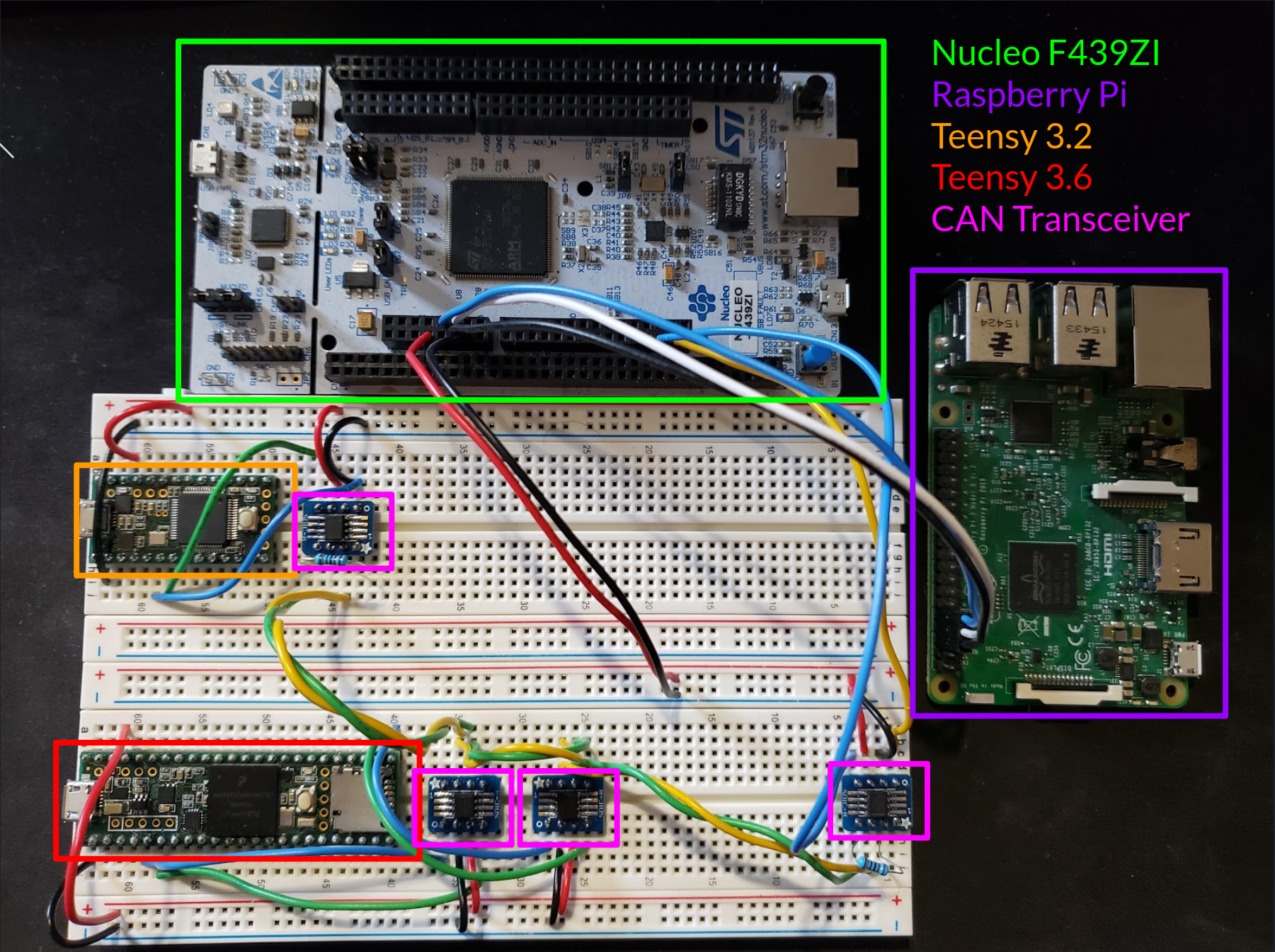
The hardware for the datalogger itself consists of a Raspberry Pi 3 paired with an STM32 Nucleo F439ZI microcontroller board. The Nucleo board was chosen for convenience and is more powerful than what is required by the application. STM32 is a common platform, so there is significant community and first-party support. This makes it easy to quickly develop applications. The Raspberry Pi was chosen for similar reasons. In addition, the Raspberry Pi runs a full operating system with a modern filesystem, making it more robust for use on the dynamic environment of a racecar. The Raspberry Pi also has on-board wireless in the form of WiFi and Bluetooth, although WiFi was used for this project.
Obviously, testing using an actual car is cumbersome, so a smaller testbed was created. This testbed contains the hardware for the datalogger as well as other microcontrollers producing CANbus data. This setup, shown above, is useful for end-to-end testing and validation. A Teensy 3.6 is used as a mock engine computer (ECU) and sends the same CANbus messages as on the real vehicle. The actual values sent are largely meaningless, but still useful for validation.
While the microcontrollers used in this project are all equipped with CAN peripherals, a CAN transceiver is still required for handling the physical layer. The TI SN65HVD232 is a good choice since it runs on 3.3V, the same voltage that the microcontrollers use.
Software
Application Architecture
For the mock ECU, a simple loop that writes CAN messages at a specific frequency is sufficient. Most of the data fields are left static since this is sufficient for end-to-end testing. To keep things slightly interesting, the value for the current engine RPM follows a sawtooth wave. When visualizing later, this pattern can be confirmed.
The code running on the Nucleo board uses an event loop. Currently, there is only a single event which is triggered by having an incoming CAN message, but in the future, button presses could be recorded and processed. When a CAN message is received, the data inside is extracted and sent to the Raspberry Pi over a serial link using a custom protocol described later.
The Raspberry Pi code is by far the most sophisticated. It is written entirely in Python and makes heavy use of the threading module. A thread based model of computation makes it easy to have separate thread polling for serial messages, sending and receiving network data, and writing to the log file. The actual implementation of the threading module in Python only uses a single processing core and is more akin to cooperative multitasking than true multithreading. There are four threads in total. The first handles serial communication with the Nucleo board. The second sends network packets to the visualizer application. The third listens for network messages from the visualizer application. The final thread handles catching the visualizer up when it misses packets as part of the delay tolerance scheme.
Logging
For efficient storage and retrieval of data, the Raspberry Pi application writes all log data to an SQLite database. SQLite is an database implementation that writes all data to a local file. When pulling logs from the device, a simple scp command can be used. Querying data is done using SQL, which makes working with the data trivial. In the past, I have used many systems for writing logs in both binary and text format and this has been the most usable by far. Data is written at a rate of 2 Hz, which is enough for analysis and saves on storage space.
Visualization
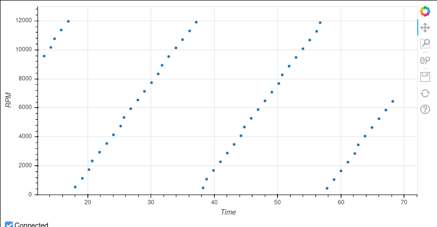
For visualization, I chose to also write the application in Python, making heavy use of a plotting library called Bokeh. The screenshot above shows the application in action As a proof of concept, I chose to only plot the engine RPM. Given that the mock ECU only sends interesting values for RPM, it works well enough. Since constantly disconnecting and reconnecting devices to test the delay tolerance was tedious, I added a simple switch to control whether the visualizer should act like it is connected or not. When disconnected, it ignore received messages and does not send any responses.
System Integration
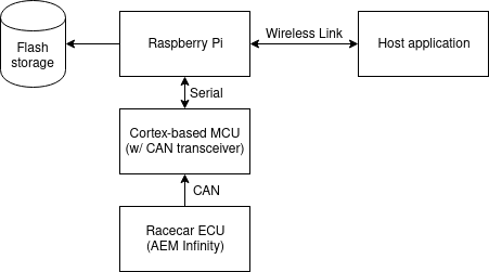
The above diagram shows the seperate hardware modules and how they communicate.
AEMnet
The ECU used on the racecar is an AEM Infinity Series 3. This ECU uses a standard implementation of a CANbus, which AEM markets as AEMnet. The messages sent by the ECU are documented and published. There are only a few messages which are of interest to us. These messages cover the essential vehicle parameters like engine RPM, coolant temperature, fuel pressure, and speed to name a few. Extracting the data is a simple matter of following the format specified by AEM.
The full list of parameters tracked is:
- Timestamp
- Sequence number
- Engine RPM
- Throttle Position
- Intake Air Temperature
- Coolant Temperature
- Air-to-Fuel Ratio
- Speed
- Gear
- Battery Voltage
- Manifold Absolute Pressure
- Fuel Pressure
Serial Protocol
To ship data between the Nucleo and Raspberry Pi, a serial connection using a UART is used. The packets sent are quite simple, consisting of a start signal, a sequence number, up to four CAN messages, and a CRC32. The start signal is 0xFEEDFACE and serves to denote when to start reading. The sequence number is useful for making sure data is not stale. Multiple CAN messages are shipped together to reduce the overhead of messaging. In reality, most of the messages are received at the same frequency, so this is a useful optimization. UART can only do parity checking for error detection which is quite lackluster. I added a CRC to make sure that the communication is reliable. The STM32 processer which I a using has a hardware CRC unit which I have taken advantage of. It does the CRC using a big-endian order rather than the usual little-endian order used commonly, which made it somewhat difficult to get started. Once I realized this, it was straightforward to get the CRCs to agree between the Nucleo and Raspbery Pi.
Network Protocol
For the networking protocols, UDP was chosen since it is better suited to the application. A stream based protocol like TCP will break down when there are frequent disconnects and the connection is spotty. The datalogger sends messages at a fixed rate of 1 Hz to a known network IP and port. These messages contain the current system parameters as well as a timestamp and sequence number. This is done regardless of whether a “client” application is connected or not.
The visualizer application listens for the packets sent by the datalogger. On reception, it plots the data found in the packet. Additionally, it tracks the sequence number found in the packet. It will continuously send acknowledgement messages using this sequence number to the IP address of the datalogger.
The datalogger listens for acknowledgement packets from the client to determine whether it is connected and which messages it has received. When a sufficiently large gap is detected in the acknowledgement messages, the range of missing sequence numbers is tracked. For example, if the last known ack from the client was for packet 40 and a recent ack is received with sequence number 90, then the range 41-89 is saved.
When a range of missing values is found, a separate thread than the usual network send thread queries the SQL database for the missing rows and sends them to the client. I went through several iterations of the best way to these catch up messages. The first was to send them in reverse order, so using the earlier example, packet 89 would be sent, followed by 88, then 87 and so on. This worked but runs into the problem that disconnecting during the catch up sequence still leaves a large gap. Eventually, the scheme that I came up with was to divide up the missing packets into groups of eight (i.e [41,49], [50-58] …). From these groups I send the first packet first (41, 50, …), followed by the last (49, 58 …). After this the middle packet is sent, and I continue to send packets within the group. By doing this, first “low resolution” data is sent, but more data points are added to fill in the gaps giving a better idea of what the vehicle was doing.
Prior Work
Dataloggers for this field are not a new idea. AEM, the company which makes the ECU used on the vehicle, even has a first-party one, but it is costly. Our team is on a budget, so existing solutions which cost a significant amount are off the table. For this reason, developing an in-house datalogger is a valuable use of time. The wireless connectivity and delay-tolerant networking scheme are novel. I have not seen an integrated solution for this, although I’m sure that something exists for actual car manufacturers to use.
Strengths and Weaknesses
Strengths
- working proof-of-concept
- cheap hardware when compared to existing solutions
- logging to a database makes working with the saved data easy
- wireless connectivity makes it easy to monitor car in real time
- delay tolerance allows for disruptions of service without breaking anything
Weaknesses
- only tested using mock ECU
- visualizer only shows RPM for now (this is trival to fix)
- will require further hardware development to use on the racecar
Contributions
I did everything.
Conclusion and Future Work
I believe that this datalogger is useful for testing of the racecar. It should be easy to integrate with the vehicle’s CANbus and will allow the team members to have a better idea of what happens on board. The wireless component could definitely be useful for quick diagnosis of problems and monitoring of important system parameters. Of course, there is still some work to be done. For one thing, a hardware package suitable for the vehicle must be developed. This has to include power delivery and conversion from the 14V from the car’s alternator to the 3.3V required by the microcontroller. A 3D-printed case will likely be created to contain everything in one easy-to-use box. The visualizer application will likely see some changes as the team discovers the most useful views. Overall, I consider this a huge success and it should allow significant progress on the vehicle.